
Pump Station Demo

Pump Station Demo

A simulation-based engineering demonstration of a pump-station control system built around a Siemens S7-1200 CPU 1214C. The TIA Portal V19 project includes analog level scaling and range diagnostics, AUTO and MANUAL modes, level interlocks, pump running-feedback supervision, and timeout-based fault handling. The WinCC Unified HMI provides the main operator screen and a settings interface with numeric-keypad input and value validation. The report records 15 functional test cases with PASS status in S7-PLCSIM V19. Technical documents and the project archive are available for download. A separate Falmont Edge browser demo illustrates the HMI interaction model; it is not a Siemens Runtime instance and is not connected to a physical PLC. No physical pump station or field commissioning is claimed.

Automation · PLC / HMI · pump-station

DEVELOPMENT

Pump Station Demo
Pump Station Demo
Pump Station Demo
Pump Station Demo
Pump Station Demo
Pump Station Demo
Pump Station Demo
Pump Station Demo
Pump Station Demo
Pump Station Demo

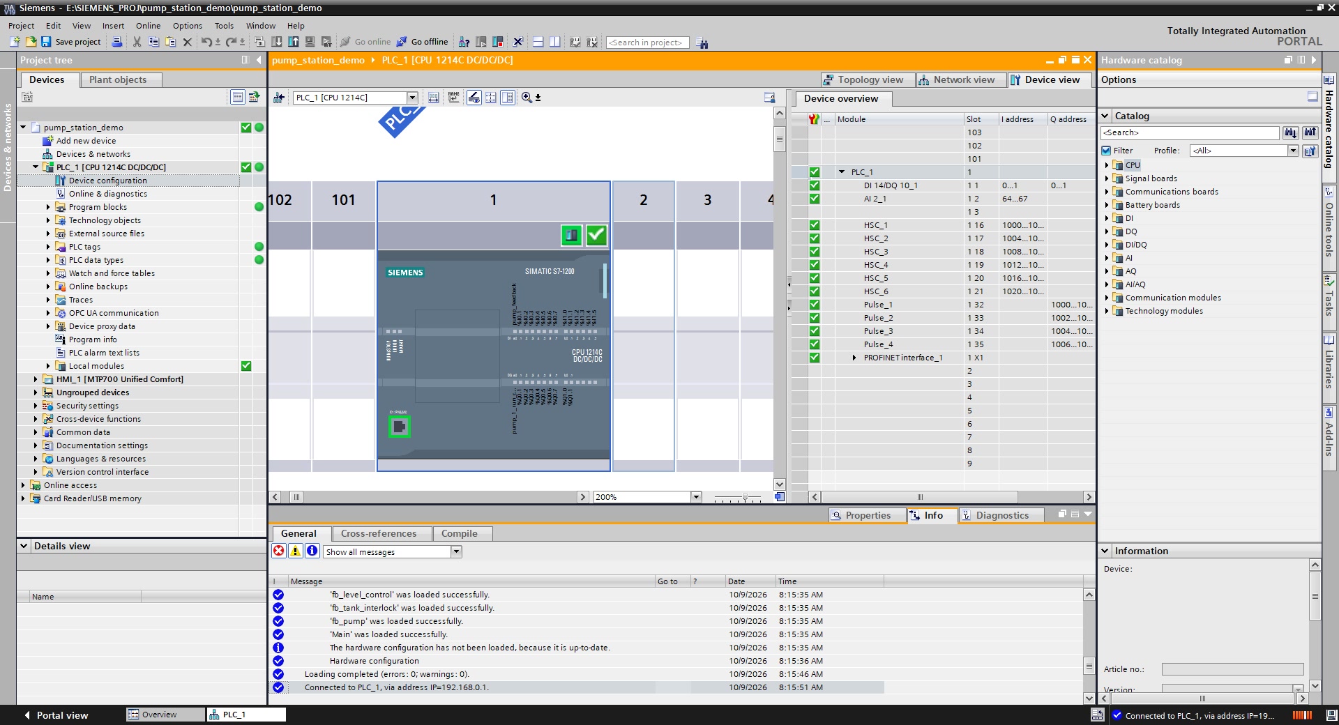
PLC Hardware Configuration

Device Configuration shows the Siemens PLC and its available integrated interfaces. This is a TIA Portal hardware-configuration view, not evidence of physical installation.

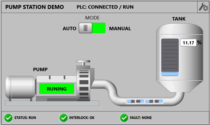
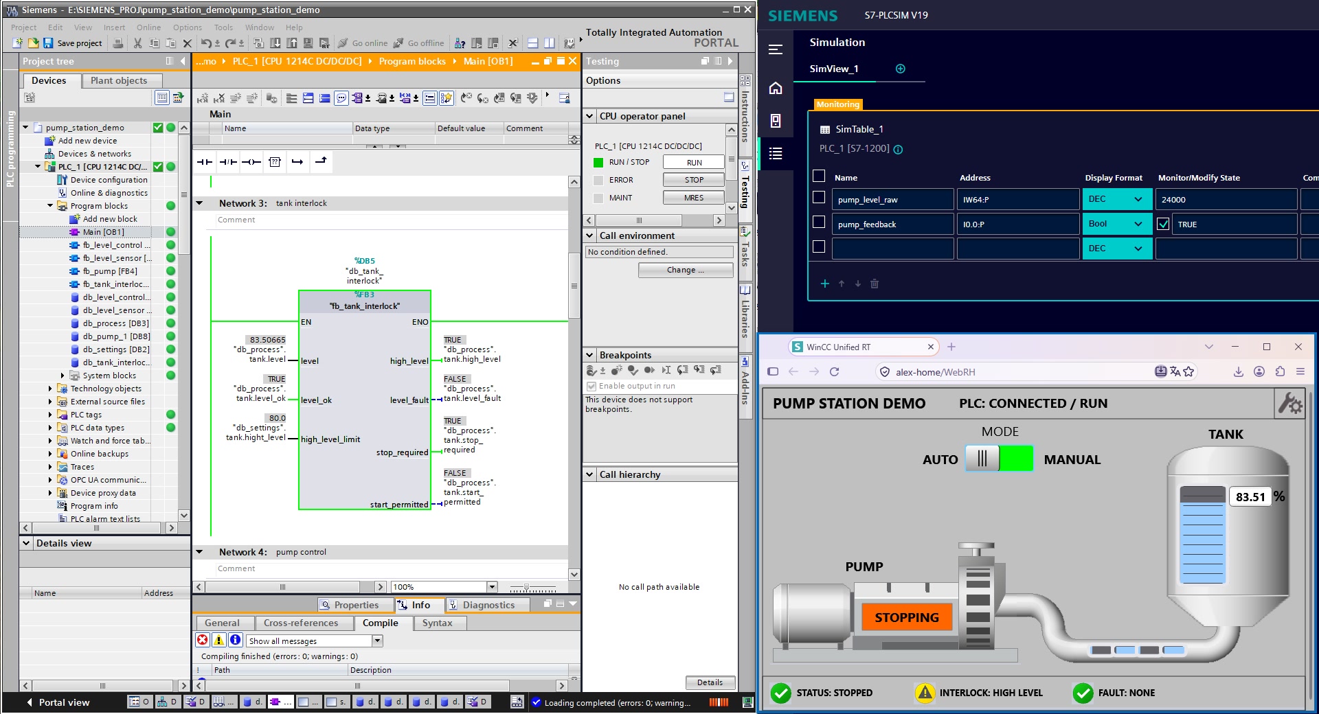
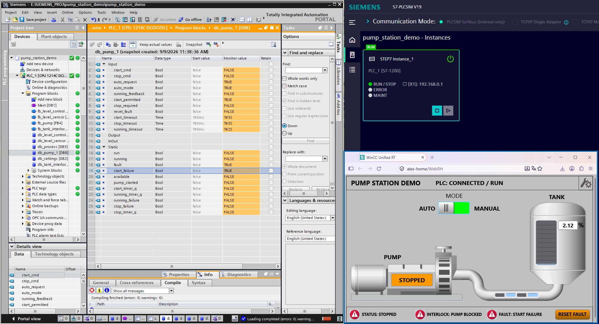
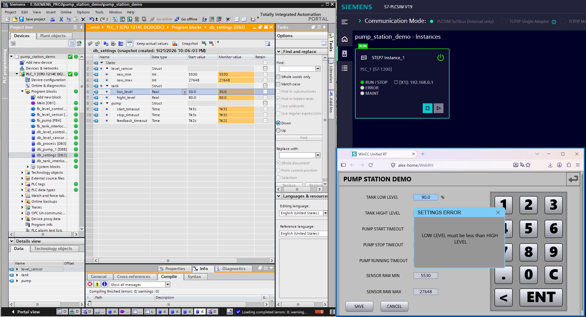
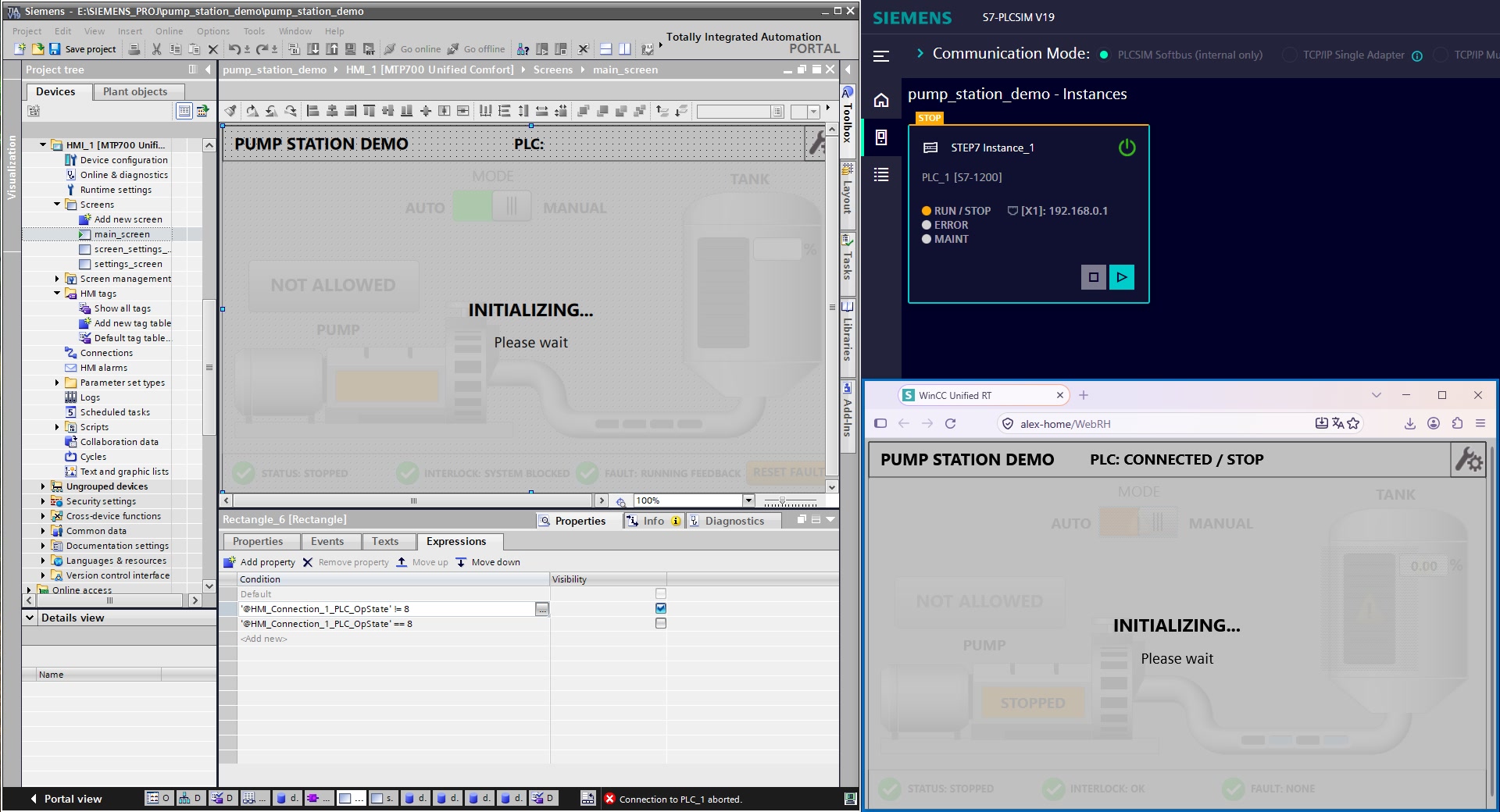
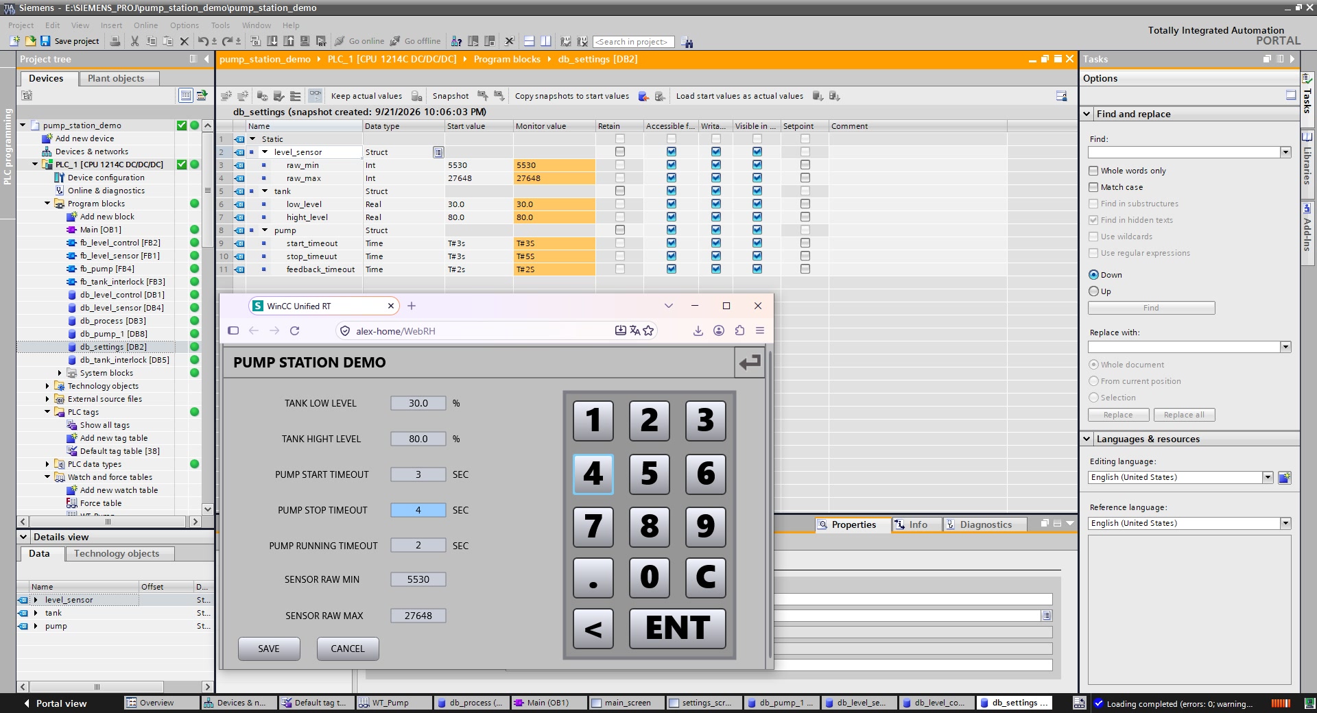
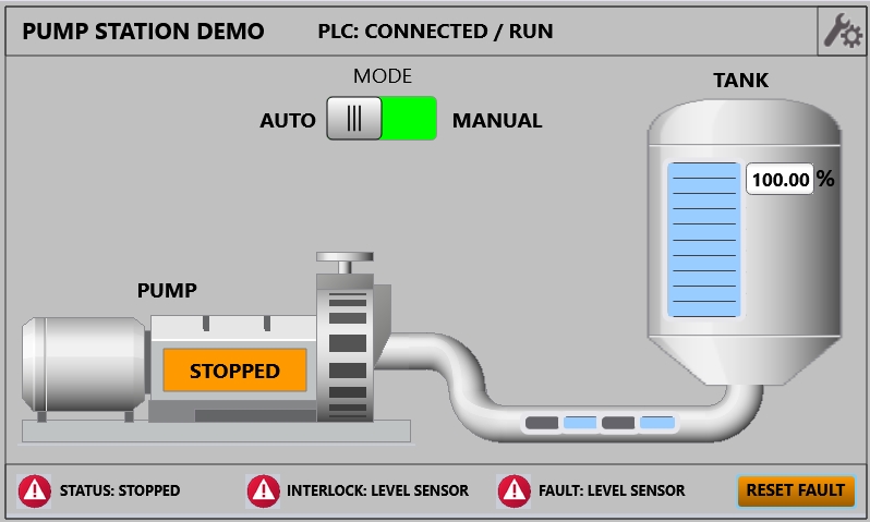
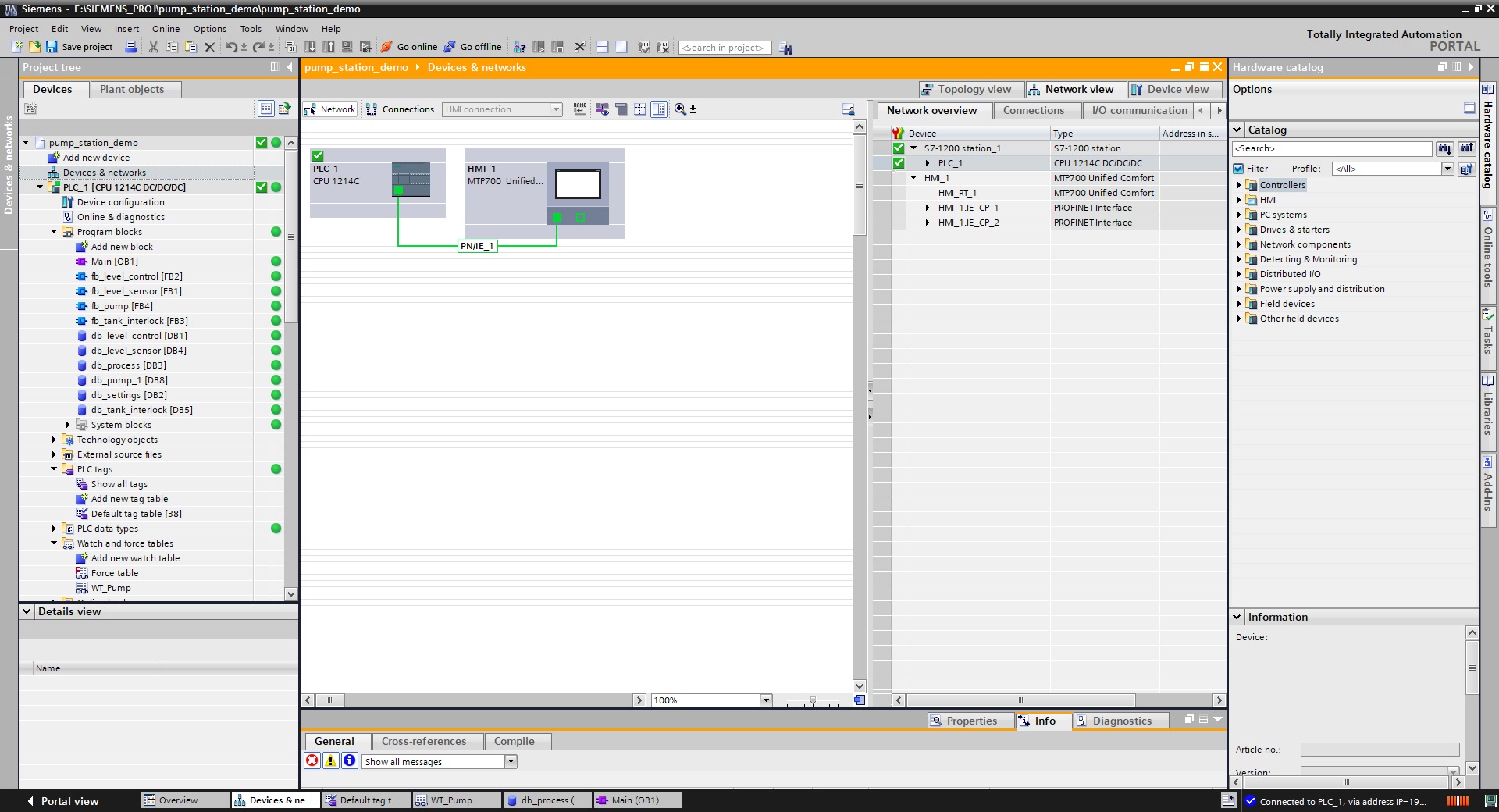
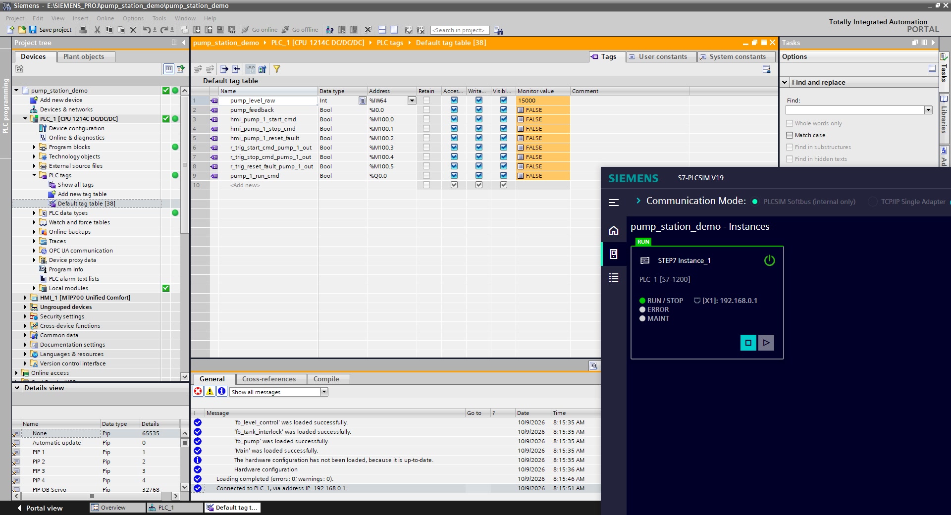
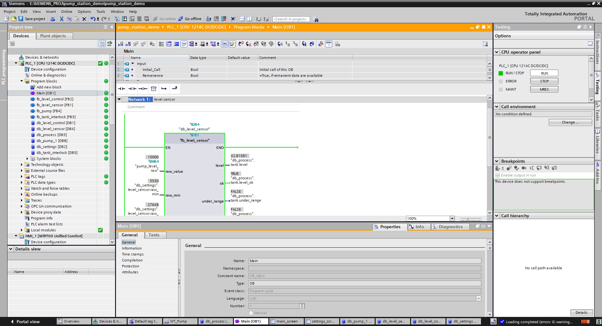
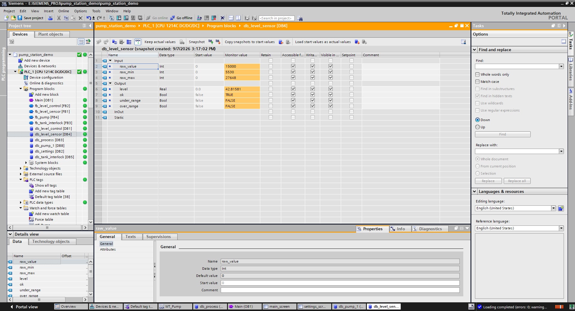
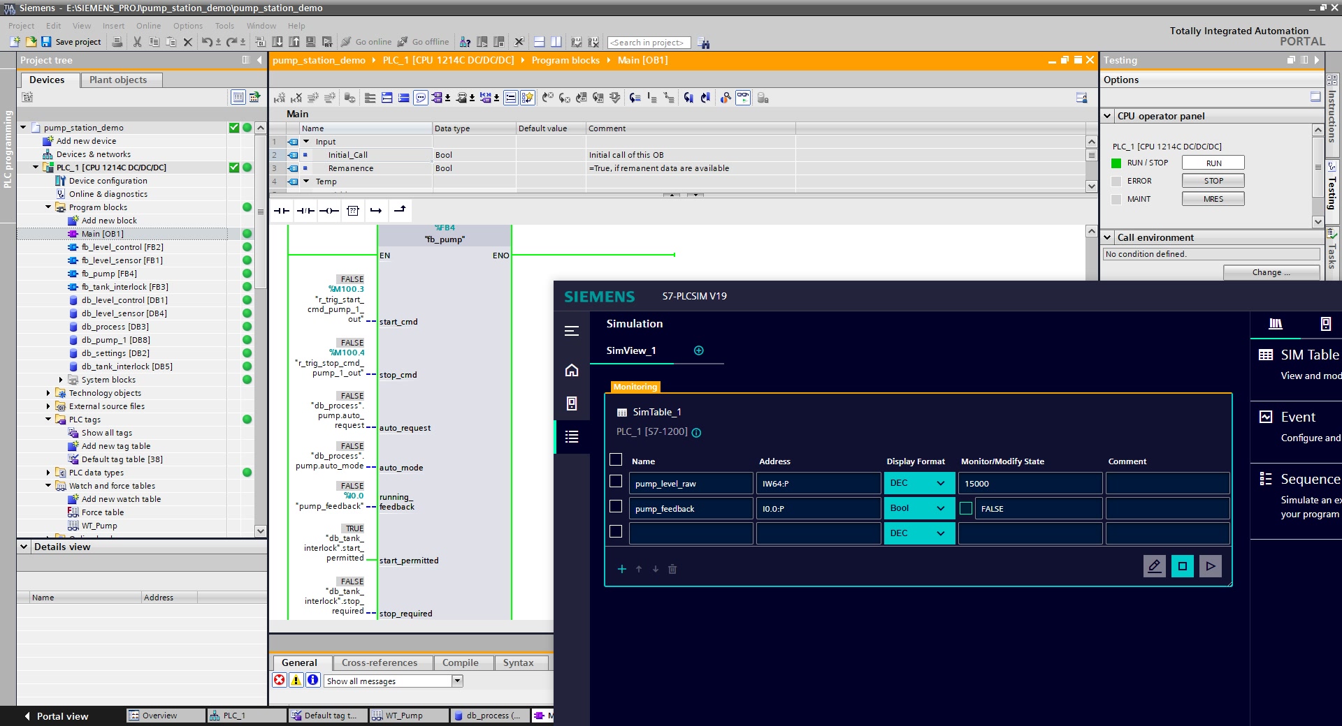
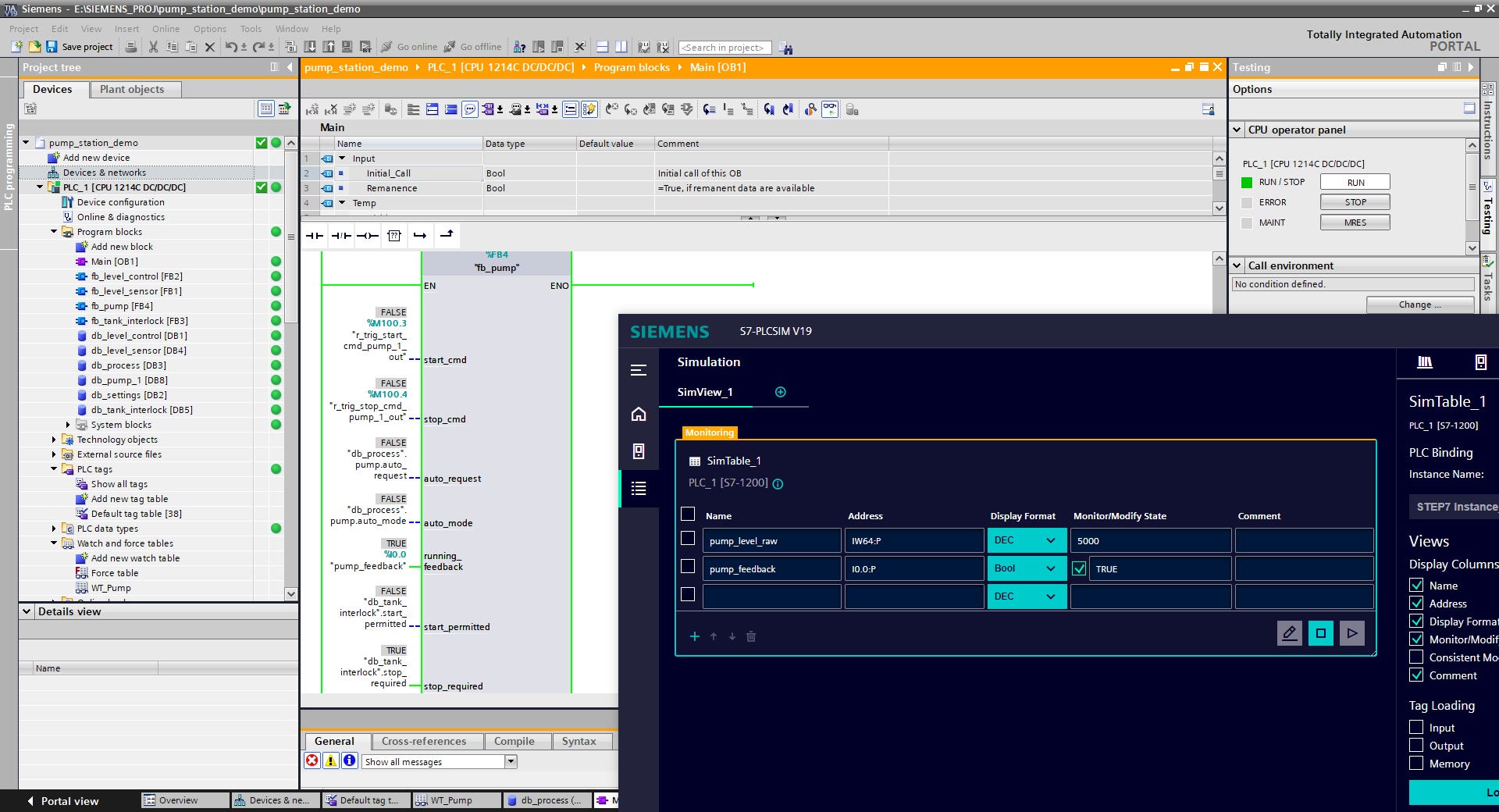
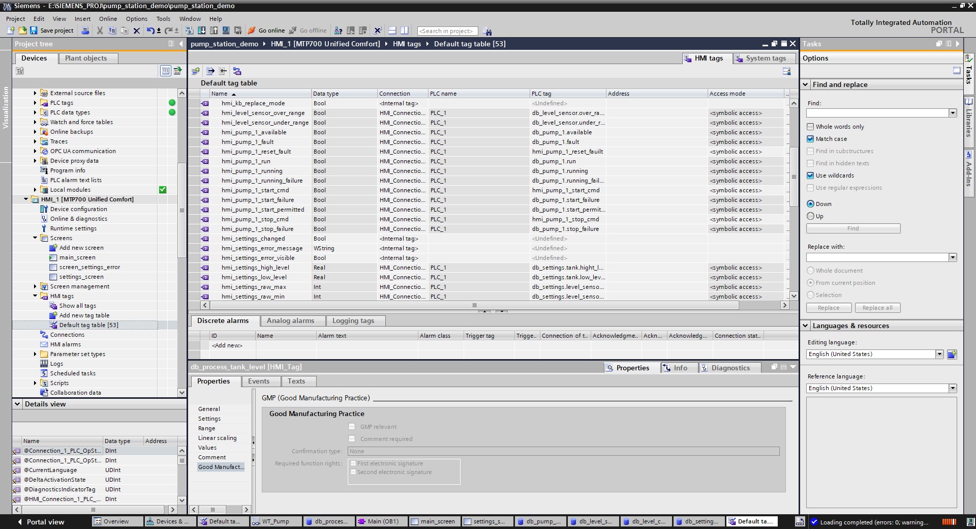
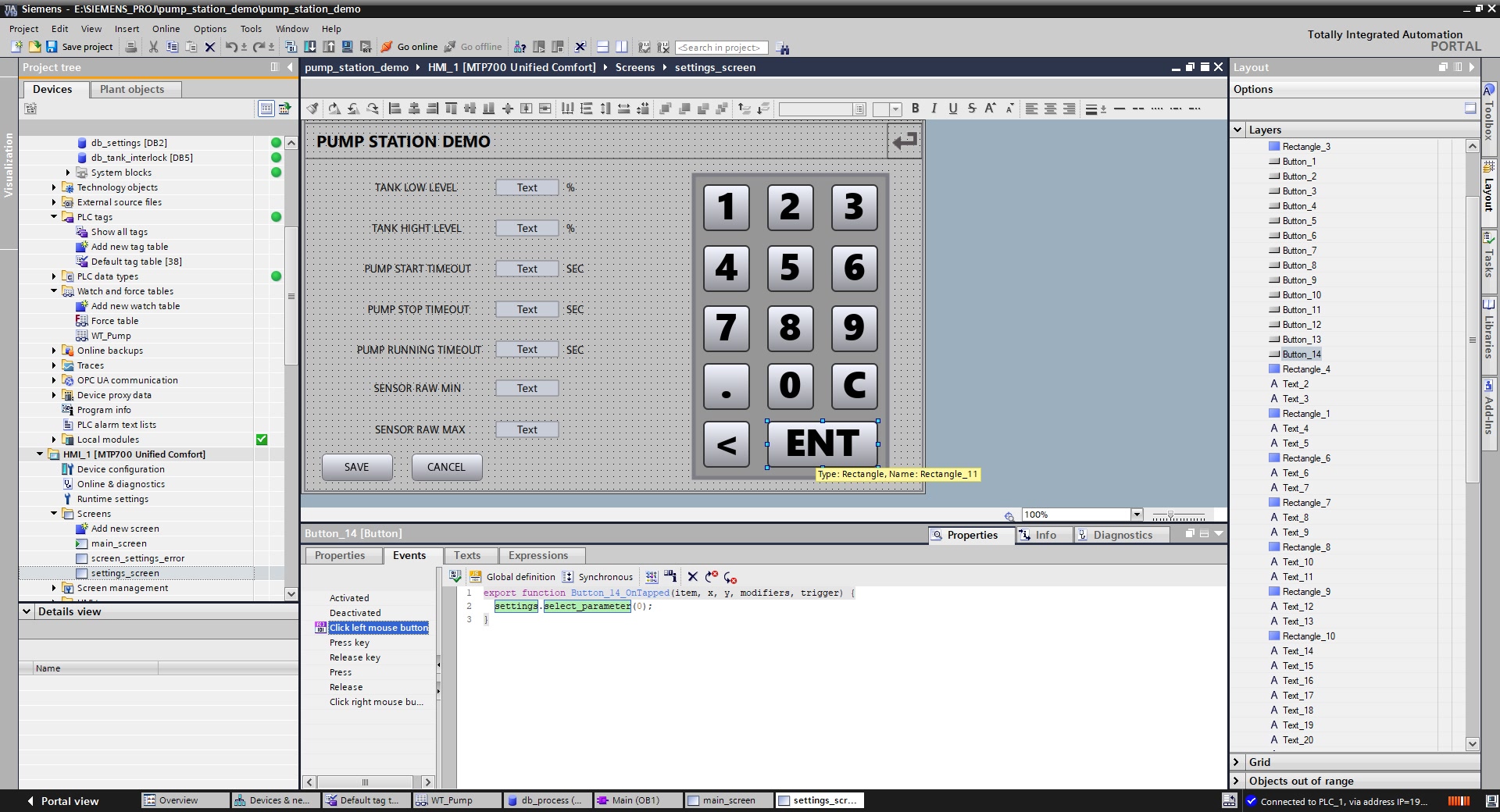
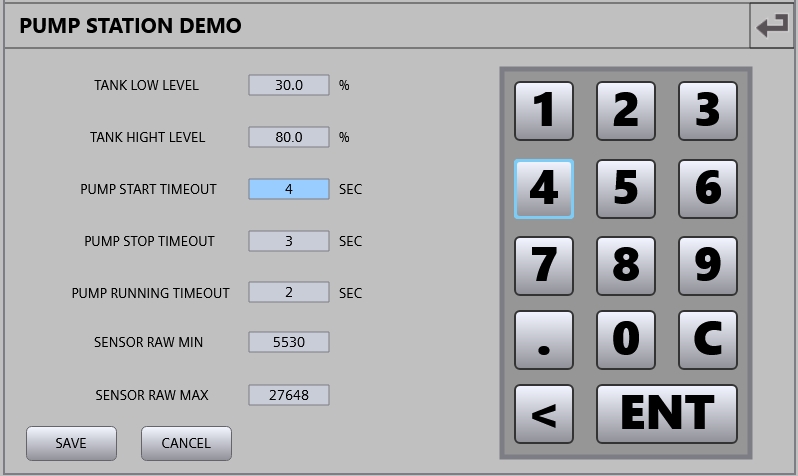
Development covered the Siemens S7-1200 CPU 1214C configuration in TIA Portal V19, the cyclic OB1 program and function blocks for level and pump control. PLC/HMI communication and tag tables were configured, and LAD logic responses were observed in S7-PLCSIM V19. The screenshots show the project in TIA Portal and WinCC Unified, along with selected simulation states. Results of the 15 functional checks are documented in a separate report.
Result

Pump Station Demo
Pump Station Demo
Pump Station Demo
Pump Station Demo
Pump Station Demo
Pump Station Demo
Pump Station Demo
Pump Station Demo
Pump Station Demo
Pump Station Demo

Integrated Engineering Workstation

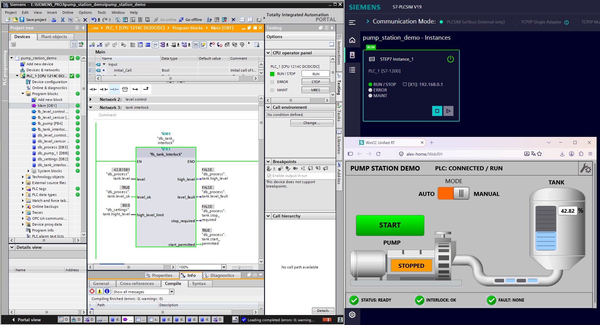
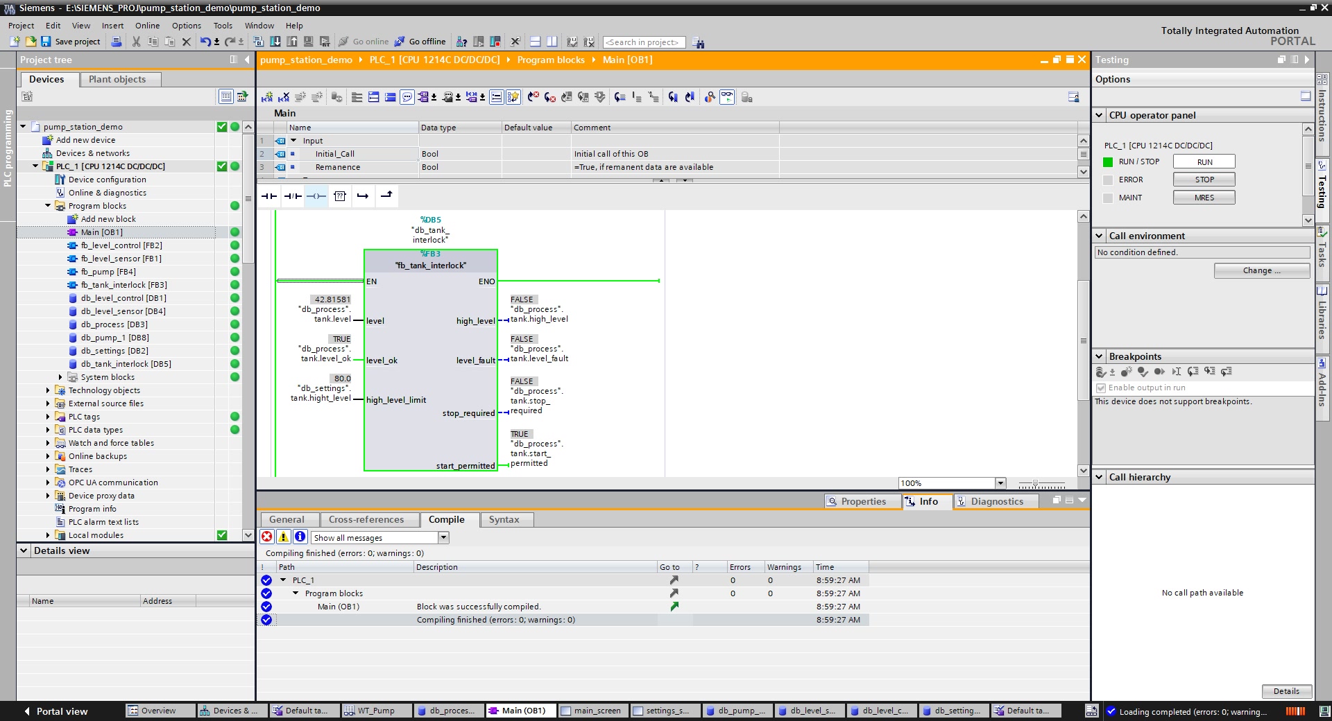
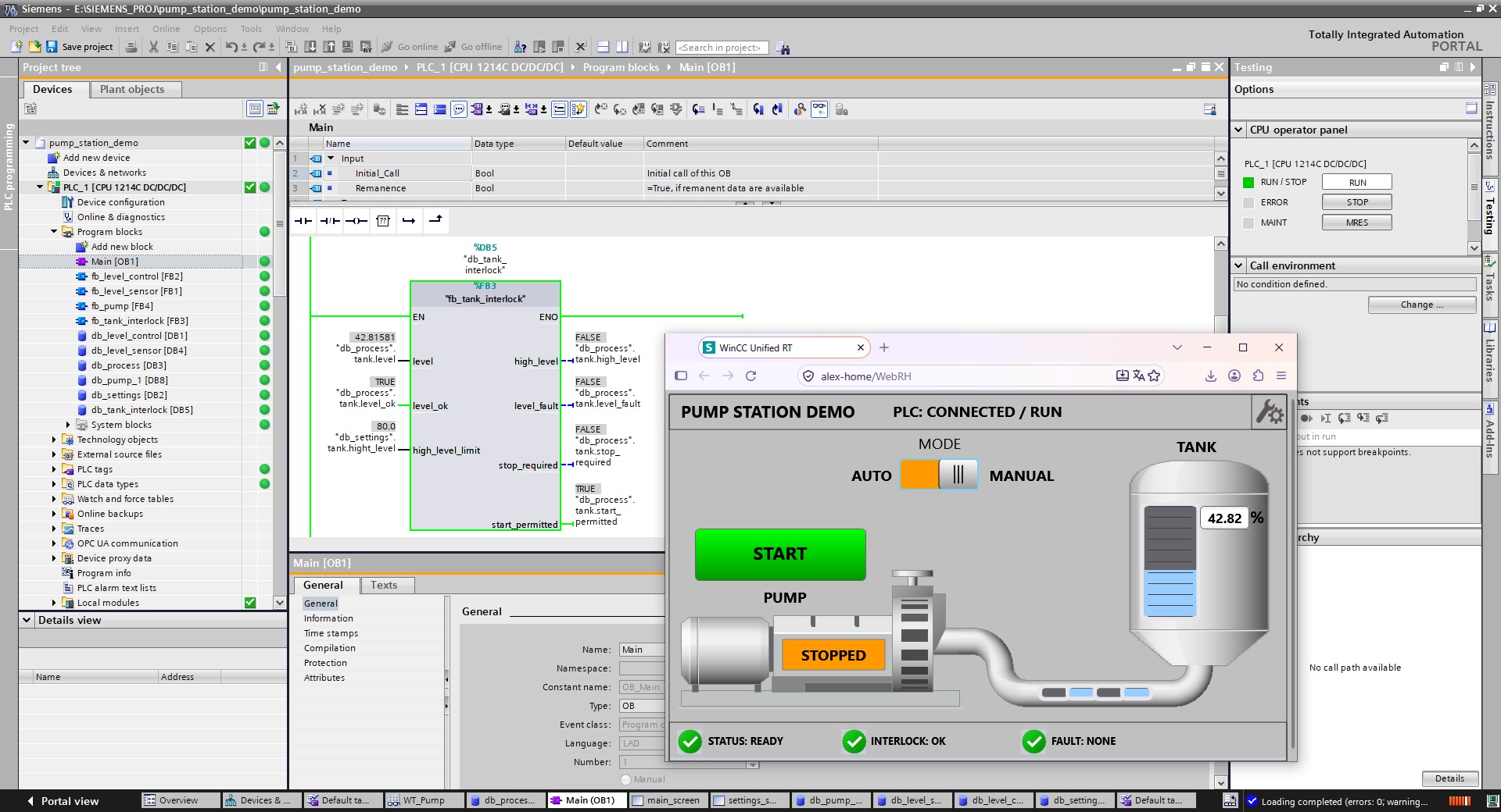
The composition shows OB1 LAD logic in TIA Portal, S7-PLCSIM in RUN, and the browser HMI in MANUAL. The HMI shows the pump stopped and a 42% tank level. This is an overview of the simulated engineering environment.

The final stage brings together the PLC program, controller simulation and WinCC Unified operator interface. The selected frames show system states and diagnostic scenarios covered during functional verification. Results of the 15 checks with PASS status are documented in the separate Test and Verification Report. The Falmont Edge browser demo is available for interactive exploration, but it is not a Siemens Runtime instance and is not synchronized with the original PLC. No physical pump station or field commissioning was included in the project.

LIVE DEMO · SIEMENS

Pump Station HMI Demo

Interactive browser simulation of the Siemens WinCC Unified operator screen based on the Pump Station project.

Engineering Documentation

System description, control and signal specification, functional verification report, and the Siemens project archive. Documents are available in Russian, English, and Uzbek.

01 — Project Description

PLC/HMI architecture, level processing, control modes, interlocks, diagnostics, and simulation limitations.

RUPDF
ENPDF
UZPDF

02 — Control and Signal Specification

Four worksheets: I/O List, Interlocks, Alarms, and Settings. Includes signal addresses, interlock conditions, diagnostics, and configuration parameters.

RUXLSX
ENXLSX
UZXLSX

03 — Test and Verification Report

A five-page report with 15 functional test cases T-01–T-15, PASS results, and selected simulation evidence screenshots.

RUPDF
ENPDF
UZPDF

Appendix A — PLC Program Structure (OB1)

A separate PDF containing the OB1 program organization block export.

Main.pdfPDF